Embedded Meets the Internet: Build Your Own Air Quality Meter
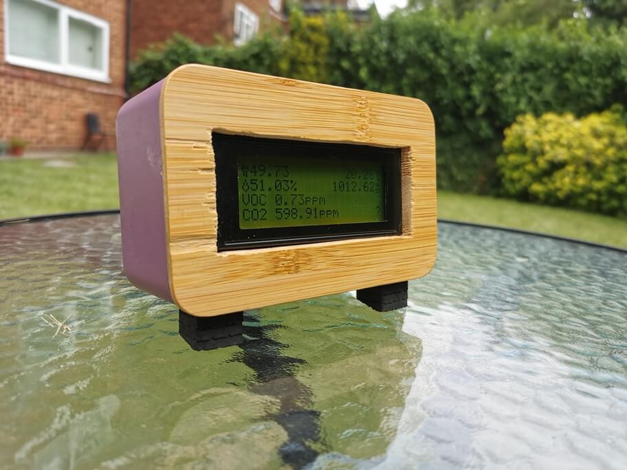
The Finished Product - quite rustic!
This article was recently featured in Hackaday and Diyode!
I’m bored. I’m sure you are too. I’m personally very thankful that I can still work through this strange period - but there are still hours in the day to fill. I wanted a personal project, so I thought about remote working and the health impacts. Most offices here have air handling units, air conditioners, and fans to keep air circulating. Most residential flats like the one I rent do not. Given I now spend close to 24 hours a day sat in this flat, air quality seems important. I looked up the cost of air quality meters and they’re either fairly pricy or fairly useless. I wanted one that I could graph over time. I decided to DIY one! This wasn’t intended to be a super serious project, just a bit of fun and an opportunity to learn more about embedded systems.
In the end, I built a little unit I think looks pretty nice given my limited DIY skills that:
- Displays realtime air quality data on a LCD
- Reports realtime air quality data to a MQTT broker
- Allows realtime monitoring on any device that can do MQTT.
I also involved a Raspberry Pi in this party that:
- Persists data to an InfluxDB instance
- Hosts a Grafana instance
- Reboots occasionally and crashes if you look at it funny - just Raspberry Pi things.
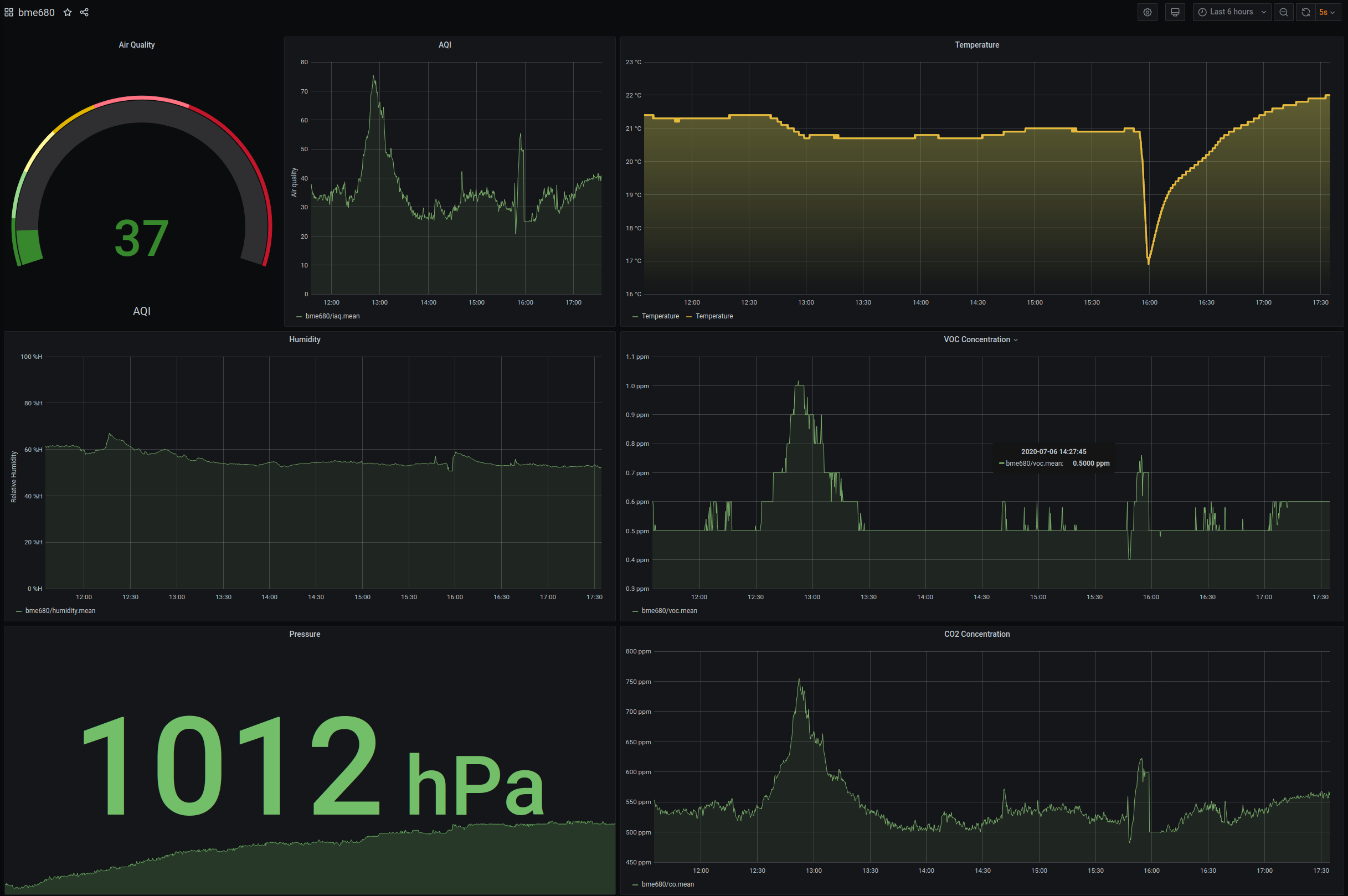
The IMO super pretty graphs it makes in Grafana - that huge dip in temperature is when I took it outside to take photos of it for this article!
The Parts
4MB Flash MIINI WEMOS D1 Lolin32 ESP32 Dev Board
I have worked with Arduino in the past - and have always found them to be a really fun tool to have in the arsenal. They’re cheap as hell and very useful in many electronics projects. I wanted something that was similar to work with in capability, but wanted more - namely I wanted to connect it to the internet! There are ways to connect an Arduino to the internet, but a far more seamless solution presented itself inside a gift my lovely fiance got for me a few months back - the Odroid Go! The Odroid Go is portable games console styled after the Gameboy and is capable of playing the games of many retro consoles. It also has a pretty prolific hacker community - since it is powered by a somewhat custom ESP32.
The ESP32 sounded incredible! two 240MHz cores + a third ’low power’ core to keep things ticking while it’s asleep, 520KB of SRAM, WiFi, Bluetooth, 34 GPIO Pins, 12 bit ADC, SPI and I2C support - it really sounded like the perfect hacker board. Even the ESP32 data-sheet does a good job of selling the applications of a solution like this, listing IoT Sensor Hub as its top application. Best of all, it’s unreasonably cheap! I picked up what I am pretty sure is a clone of another dev board manufactured by WEMOS from eBay for 7GBP delivered.
You can write code for the ESP32 in numerous ways - but the way that I was interested in was using the Arduino IDE - since I already had some experience with it in the past.
2004 I2C LCD Display
I wanted to have some sort of external display that would show the realtime values at all times. I considered going for a full colour display here, but decided that for simplicities sake I’d go for one of the old fashioned, text only ones that was probably intended to go into some industrial control hardware or a VCR. It also has the benefit of being fairly low power in comparison to a permanently backlit full colour TFT display.
The one I got has a lovely interface board already soldered on that allows you to talk to it using I2C - and also has a bright green backlight that my fiance has lovingly nicknamed the ‘Shrek’ lamp.
CJMCU-680 BME680 Module
This component it what sparked this whole project off. My phones assistant fairly regularly notifies me of Kickstarter or IndieGoGo projects that are fundraising - and this time the advertised product looked fairly interesting. It was the Metriful Sense board - an Indoor Environment Monitor board. It features a Light sensor, microphone, and the Bosch BME680. I was considering backing the Metriful Kickstarter and I’d encourage you to do so if this sounds good to you - however I decided I didn’t care about light and sound, didn’t want to wait months for it to shop, and only really cared about air quality, so I went to eBay and found that the BME680 is being sold on breakout boards for around 15GBP - shipped first class, so I got that instead. This component is actually the most expensive part of the build (I paid 16GBP) - but it is a pretty cool sensor.
The BME680 measures temperature, pressure, humidity, and gas resistance (how conductive the gas is) - and can offer you these values raw, or you can use a closed source Bosch library called BSEC which uses these 4 values and some magic sensor fusion tech to compute an Air Quality Index, as well as a guess at the Co2 and VOC concentrations in the room.
Enclosure
For an enclosure, I decided I wanted something fairly roomy - having been burned by trying to make miniature projects in the past. I wanted something that would fit the aesthetic of my flat, and something that was fairly easy to work with. I ended up settling on a plastic lunchbox which has a lovely wooden lid that press fits into the plastic from a shop called Flying Tiger. Really, any box that will fit the components and you can drill will work. I think it turned out pretty nice even with my absolutely terrible woodworking skills.
Battery Choices
I wanted to be able to transport this meter around the house and have it continuously measure for a period after it was unplugged. I wanted it to have reasonably good battery life. I also try to reuse things I have that would be ’e-waste’ otherwise and I settled on a 3000mAh 18650 battery that I had lying around that was in use for a high current application prior, but now had developed too high of an internal resistance to really push amps. Perfect for this project then, since the entire project will sip around 80mA in its completely unoptimised form, and this could easily be significantly reduced. In reality, the battery lasts around 30 hours. All I needed to purchase here was an 18650 holder.
Raspberry Pi or other server you control
The ESP32 is a very powerful dev board, but in order to persist large amounts of data and to make it accessible in something like Grafana we’re going to need something a bit more powerful! I had a Raspberry Pi 3b+ sitting in the ‘one day I’ll find a use for you’ box I have and decided this was a perfect use. It can be my MQTT broker. It can even perform double duty and host Grafana for me. I did consider hosting all of this on the server that hosts this very website (A Scaleway instance) - but didn’t want to pollute that environment too much if I ended up getting bored of this project.
I’d like to stress here something that I learned the hard way - a good quality power supply is an absolute requirement for any Raspberry Pi. Lower quality power supplies just aren’t beefy enough to really supply the Pi when things really get going and you’ll find yourself chasing ghosts. Get a decent power supply!
The Build
I2C Components
I’ll provide a quick and dirty primer on I2C: It’s a way of attaching peripherals to microprocessors over short distances. It’s pretty slow topping out at 5 Mbps - but is nice since it has extremely simple wiring (just 2 data wires!) and you can chain devices. Effectively, we just need to connect the SDA and SCL pins (along with power) between the components and the ESP32 and the hardware portion is finished. When we want to connect two devices, we just connect all 3 in a chain (connect all the SDAs together, connect all the SCLs together). The only other thing we realistically need to take into account is the address. Each I2C Peripheral will have an address that identifies it on the bus. These addresses are not unique. If you purchase two of the same peripheral, you’ll probably find they have the same address in their default configuration. This means that you cannot ’talk’ to each device independently if they’re on the same bus. There are a couple of solutions to this problem: the simplest being peripherals that feature an ‘address select’ jumper which will allow you to select a secondary address to use instead of the first, and other peripherals will be reprogrammable so you can change the address freely. YMMV.
So, to connect our I2C components up, just connect all the SDAs together, and all the SCLs together. Pretty simple!
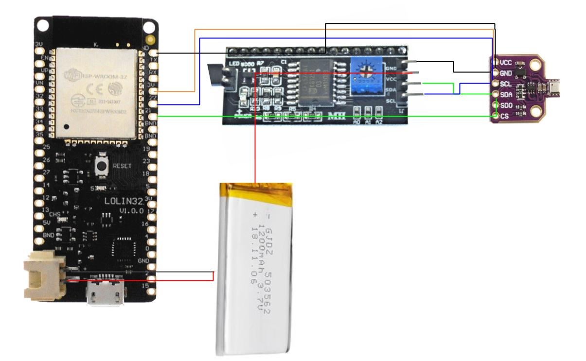
Connections - basically connect all the SDAs up, connect all the SCLs up, connect VIN of the BME680 to the 3v pin on the esp32, connect the VIN of the LCD to the positive lead of your battery, connect the battery to the Lipo battery connector on the esp32, and wire up the grounds! Diagrams really aren't my strong suit.
Once we’ve done this, it’s time to power them.
Power considerations
In order to figure out how to power this all, I needed to know the power requirements of each component. In the case of the ESP32 - I am using a dev board which will have its own power draws on top of the ESP32 itself for things like the serial to USB chip as well as for the charging circuitry since it features a LiPo charging circuit, so the current requirement is from the ESP32 data sheet directly - since this weird clone board I got doesn’t seem to have a datasheet that exactly matches it. Same goes for the LCD and the CJMCU-680. This is the downside of buying strange boards from Aliexpress I guess! For this specific project, I experimented a little and did some voltage/current testing and got these values.
| Component | Input Voltage Requirement | Current requirement |
|---|---|---|
ESP32 Board |
3.7v from LiPo input | 70mA |
2004 LCD |
5v but runs fine at LiPo voltages too in my case | 50mA with backlight |
CJMCU-680 |
3.3v | 10mA |
Let’s start with the CJMCU-680. It runs at 3.3v and needs 10mA, but only very briefly. As far as I can tell, gas resistivity sensors like the one found in the BME680 heat up a plate inside the component to ‘activate’ some material that reacts with various gasses - changing the resistance of this sensing material. The measurement of this resistance is how the sensor determines the gas resistivity. The initial heating phase which happens in less than 0.1s according to the datasheet is the highest current phase, at which point the current draw drops dramatically. I connected this component to the 3.3v and GND pins on the ESP32 and it seemed to work so that’s how I left it.
Next up is the ESP32 itself. The dev board I got helpfully provides two ways to power it. You can either just connect a USB power supply to the onboard MicroUSB port which powers the whole lot, or you can connect a Lipo cell to the onboard battery connector, at which point the onboard MicroUSB port doubles as a pretty bad battery charger. The charger on my board seems to charge the battery at around 400mA with all other components attached and working - which means it’s probably supplying 500mA max (respecting the USB spec for once!). I went with the Lipo option, but this has a small downside - the 5v rail that the board supplies then just doesn’t seem to supply enough current to power the LCD.
For the LCD, what you’d probably want to do is engineer your own power solution that bypasses the crappy one found on the dev board. You might get your own step up converter that will take the 3.7v from the Lipo and boost it to 5v with some current rating that makes sense (1 amp is more than sufficient). You can then also get your own LiPo charging circuitry that will charge the Lipo at whichever rate you like rather than the rather slow but safe 500mA charging rate. You could go belt and braces and add on a low dropout circuit which cuts the battery connection if its voltage drops below something like 3v - since anything below this and you’ll start to enter explodey battery territory. In fact, you can buy a single circuit board that will do all of this for you in a single integrated solution. Something like this 5v power bank module or this LiPo charge circuit would likely do. What I did and do not recommend you do is just connect the LCD directly to the LiPo. This means I have completely worked around the low dropout protection the ESP32 already has which is a Bad Thing(tm) - but for my given use case (almost always plugged in, rarely without power for more than 12 hours, very large battery) - I’m happy with it. In either case, make sure you connect the ground of the LCD to a ground on the ESP32 - you must always common (connect) grounds when using something like I2C.
Onto the battery! As previously discussed, I used an 18650 I had lying around along with an 18650 battery holder.
Enclosure
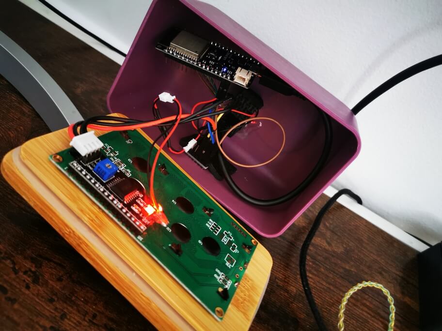
Messy internals never really bothered me!
Quick note: Woodwork is NOT my strong suit, so please forgive the tragic method that I describe. I purchased a lunchbox that is a plastic box with a piece of wood that fits into the plastic box as a lid. I cut a small hole in the bottom so the BME680 sensor could breathe by heating a drill bit and slowly drilling through the plastic. I cut another three of these holes on the back, one sort of MicroUSB shaped, another for a toggle switch that I use to toggle the backlight of the LCD, and another push button switch that pulls io0 low so that my dev board goes into flash mode. The hole I cut in the wooden lid is rough as hell because I do not own a jigsaw nor did I want to buy one. Instead, what I did was I drilled holes all along the edges of the wood I wanted to cut out, and then stuck a hacksaw blade through these holes and cut using the hacksaw. It took forever and there was probably a better way available to me, but this method worked in the end. Several minutes of sanding to get the LCD to press fit into the hole, and it was finished.
I glued the BME680 in place using a adhesive rubber furniture foot thing because that’s what I had to hand. If this is a permanent installation, you may want to invest in some standoffs and screws so you can mount yours properly. I found on eBay a MicroUSB ’extender’ cable, that has a male MicroUSB port on one side and a female MicroUSB port on the other. I epoxied the female side to the microUSB shaped hole, and plugged the male side into the ESP32. I superglued the 18650 battery holder in place. The ESP32 is currently just floating about on the inside of the case since I still frequently access pins on it.
It goes without saying, internally this is a bit of a mess. I don’t really mind this as it is purely a hacker project for me, something to keep me sane during Covidpocalypse. It works well and externally I’ve grown to like how it looks.
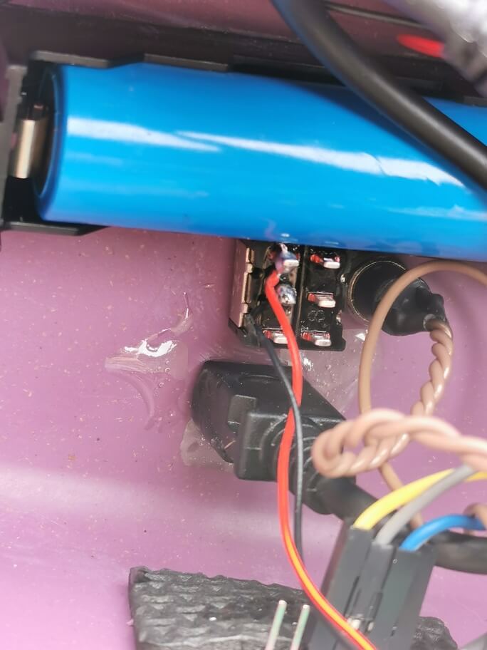
The epoxied in microUSB connector, along with the backlight control switch, the 'put it into flash mode' switch, and the 18650 cell in its holder
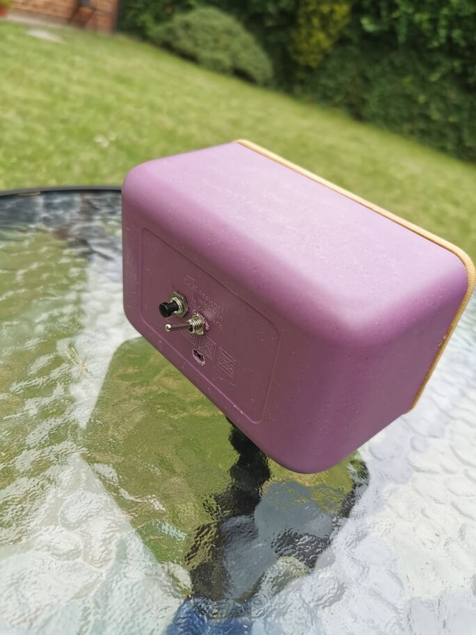
The MicroUSB hole didn't quite go exactly to plan...
ESP32 Software
Next up, we should write the code that runs the show on the ESP32. As previously discussed, I wanted to use the Arduino IDE initially since that papers over a lot of the horribleness of working with embedded systems such as this one. There is a fair bit of horribleness still - which I shall elaborate on. Due to incompatibilities between the BSEC Library and the Arduino IDE, I recommend installing Arduino IDE v1.8.10. This one works for me. Once you’ve got the Arduino IDE installed, you’re going to want to install the board tools for your board. This blog post covers installing the ESP32 dev tools. Ensure you are able to write software to the board. On my first attempt with this, the ESP32 point blank refused to accept code. I’d constantly get “ESP32: Timed out… Connecting…”. All the instructions everywhere told me to press the ‘Boot’ or ‘EN’ buttons, but my board only had one button labelled ‘reset’ and that didn’t help. What did help (and I can’t remember how or where I found to try this!) was while you are in that ‘Connecting…’ phase briefly connect the IO0 pin to ground. This seemed to kick it into ‘flash mode’, and it flashes correctly every time.
Here is a list of the libraries I used:
- BSEC Library by Bosch Sensortec (v1.5.1474)
- PubSubClient by Nick O’Leary (v2.8.0)
- LiquidCrystal I2C by Frank de Brabander (v1.1.2)
Talking to the BME680
Getting the BSEC library set up is a bit of a pain. Once you’ve successfully got ESP32 code building and flashing, you’ll need to add the BME680 library to your IDE (Download the release as a zip from the above Github Link and add it to the Arduino IDE by selecting ‘Sketch’ from the menu bar, then head to ‘Include Library’, and then ‘Add .ZIP Library…’). Once you’ve done this, close out of the Arduino IDE, navigate to where your Arduino IDE saved the ESP32 platform (usually ~/Arduino/Hardware/expressif/esp32), and then open the platform.txt in a text editor (I suggest saving a copy elsewhere so you can restore if needed!). Look for a section that looks something like the below:
compiler.c.extra_flags=
compiler.c.elf.extra_flags=
#compiler.c.elf.extra_flags=-v
compiler.cpp.extra_flags=
compiler.S.extra_flags=
compiler.ar.extra_flags=
compiler.elf2hex.extra_flags=
At the bottom of this section, add this line:
compiler.libraries.ldflags=Now that we’ve added ldflags, we need to reference them. Find the line that starts with recipe.c.combine.pattern and replace it with this:
## Combine gc-sections, archives, and objects
recipe.c.combine.pattern="{compiler.path}{compiler.c.elf.cmd}" {compiler.c.elf.flags} {compiler.c.elf.extra_flags} -Wl,--start-group {object_files} "{archive_file_path}" {compiler.c.elf.libs} {compiler.libraries.ldflags} -Wl,--end-group -Wl,-EL -o "{build.path}/{build.project_name}.elf"
Once you have done all of this, you can select one of the now available to you BSEC Example sketches (File > Examples > BSEC Software Library) and check it compiles and uploads to your board. Then consult the serial monitor to see if it works as you expected. You’ll probably find it doesn’t because nothing in life is easy and life is suffering. You should at least get an error code. If you haven’t, there is something more serious wrong. Here are a few pointers to get it working assuming you got a BSEC Error code. Well aren’t you lucky you at least get an error code! It’s nice to get an error code since you can go and look up the error code. In the documentation. Oh theres no error codes there? How about in the code? It’s closed source? Crap.
Firstly, you’ll most likely have to initialise the ‘Wire’ library with specific pins. This is easy enough, just find the Wire.begin() line and specify your pins in here:
# At the top of your sketch, below the #include lines
#define PIN_I2C_SDA 21
#define PIN_I2C_SCL 22
# Further down, in the setup() method
Wire.begin(PIN_I2C_SDA, PIN_I2C_SCL);
Secondly, my particular BME680 breakout board was for some reason configured to use the secondary I2C address, so I had to explicitly tell the BSEC library to use the secondary I2C address. Again, easy enough, find the line that contains BME680_I2C_ADDR_PRIMARY and replace it with BME680_I2C_ADDR_SECONDARY. Nice.
Talking to the LCD
This was simpler. Once again, you can head to the example code for the LCD to get a feel for what the library can do (File > Examples > INCOMPATIBLE > LiquidCrystal I2C) (the library doesn’t explicitly support the ESP32 but it seems to work fine for me!).
Example code I wrote - Arduair
Onto the good bit. I am not an Arduino expert, and I am not a C programmer, so I can’t promise this code is good. It works for me for now and I would like to tidy it up, but I present it in its current form below. It borrows code from both the BSEC Examples and the LCD examples. I’ve tried to document it with comments as well as possible.
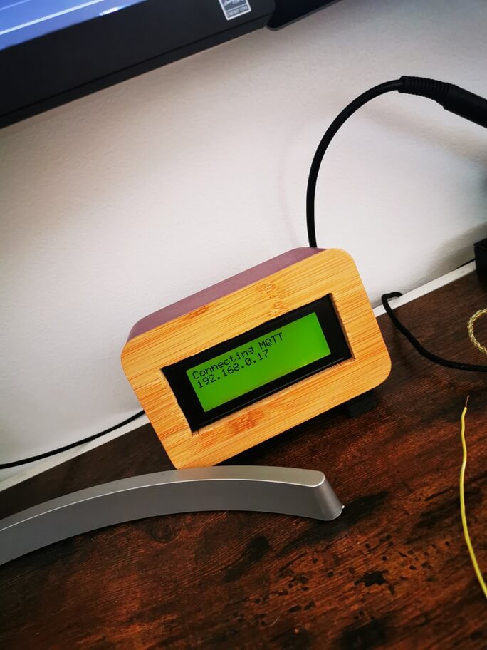
Something super satisfying seeing an oldschool LCD display an IP address...
// kn100.me - Arduairs
// Available on Github: https://github.com/kn100/arduairs
// Note: This code is provided as an example only - it does not implement authentication, TLS or anything even remotely close to security. It's probably fine if all your infrastructure lives on your local network, but you might want to consider looking into security.

#include <PubSubClient.h>

#include "bsec.h"
#include <LiquidCrystal_I2C.h>
#include <WiFi.h>
#include <EEPROM.h>

// Controls which pins are the I2C ones.
#define PIN_I2C_SDA 21
#define PIN_I2C_SCL 22

// Controls how often the code persists the BSEC Calibration data
#define STATE_SAVE_PERIOD  UINT32_C(60 * 60 * 1000) // every 60 minutes

const char* mqtt_server = "<your-mqtt-server-IP>";
const char* ssid = "<your-wifi-SSID>";
const char* passphrase = "<your-wifi-password>";

// Controls the offset for the temperature sensor. My BME680 was reading 4 degrees higher than another thermometer I trusted more, so my offset is 4.0.
const float tempOffset = 4.0;

// Configuration data for the BSEC library - telling it it is running on a 3.3v supply, that it is read from every 3 seconds, and that the sensor should take into account the last 4 days worth of data for calibration purposes.
const uint8_t bsec_config_iaq[] = {
#include "config/generic_33v_3s_4d/bsec_iaq.txt"
};

// Create an object of the class Bsec
Bsec iaqSensor;

String output;

// This stores a question mark and is eventually replaced with a space character once the BSEC library has decided it has enough calibration data to persist. It is displayed in the bottom right of the LCD as a kind of debug symbol.
String sensorPersisted = "?";

uint8_t bsecState[BSEC_MAX_STATE_BLOB_SIZE] = {0};
uint16_t stateUpdateCounter = 0;

WiFiClient espClient;
PubSubClient broker(espClient);

// The I2C address of your LCD, it will likely either be 0x27 or 0x3F
const uint8_t LCD_ADDR = 0x27;

// 20 characters across, 4 lines deep
LiquidCrystal_I2C lcd(LCD_ADDR, 20, 4);

void setup(void)
{
  Serial.begin(115200);
  broker.setServer(mqtt_server, 1883);

  Wire.begin(PIN_I2C_SDA, PIN_I2C_SCL);
  // Your module MAY use the primary address, which is available as BME680_I2C_ADDR_PRIMARY
  iaqSensor.begin(BME680_I2C_ADDR_SECONDARY, Wire);
  output = "\nBSEC library version " + String(iaqSensor.version.major) + "." + String(iaqSensor.version.minor) + "." + String(iaqSensor.version.major_bugfix) + "." + String(iaqSensor.version.minor_bugfix);
  Serial.println(output);
  checkIaqSensorStatus();
  iaqSensor.setConfig(bsec_config_iaq);

  //loadState here refers to the BSEC Calibration state.
  loadState();

  // List all the sensors we want the bsec library to give us data for
  bsec_virtual_sensor_t sensorList[10] = {
    BSEC_OUTPUT_RAW_TEMPERATURE,
    BSEC_OUTPUT_RAW_PRESSURE,
    BSEC_OUTPUT_RAW_HUMIDITY,
    BSEC_OUTPUT_RAW_GAS,
    BSEC_OUTPUT_IAQ,
    BSEC_OUTPUT_STATIC_IAQ,
    BSEC_OUTPUT_CO2_EQUIVALENT,
    BSEC_OUTPUT_BREATH_VOC_EQUIVALENT,
    BSEC_OUTPUT_SENSOR_HEAT_COMPENSATED_TEMPERATURE,
    BSEC_OUTPUT_SENSOR_HEAT_COMPENSATED_HUMIDITY,
  };

  iaqSensor.setTemperatureOffset(tempOffset);

  // Receive data from sensor list above at BSEC_SAMPLE_RATE_LP rate (every 3 seconds). There is also BSEC_SAMPLE_RATE_ULP - which requires a configuration change above.
  iaqSensor.updateSubscription(sensorList, 10, BSEC_SAMPLE_RATE_LP);
  checkIaqSensorStatus();

  lcd.init();
  lcd.backlight();
  // I wanted some iconography, so this function creates some icons in the LCDs memory. They were created using Maxpromers LCD Character Creator
  createLCDSymbols();
  connectToNetwork();
}

// Function that is looped forever
void loop(void)
{
  if (!broker.connected()) {
    reconnectToBroker();
  }
  broker.loop();
  // iaqSensor.run() will return true once new data becomes available
  if (iaqSensor.run()) {
    lcd.clear();
    displayIAQ(String(iaqSensor.staticIaq));
    displayTemp(String(iaqSensor.temperature));
    displayHumidity(String(iaqSensor.humidity));
    displayPressure(String(iaqSensor.pressure/100));
    displayCO2(String(iaqSensor.co2Equivalent));
    displayVOC(String(iaqSensor.breathVocEquivalent));
    displaySensorPersisted();
    updateState();
  } else {
    checkIaqSensorStatus();
  }
}

// checks to make sure the BME680 Sensor is working correctly.
void checkIaqSensorStatus(void)
{
  if (iaqSensor.status != BSEC_OK) {
    lcd.setCursor(0, 0);
    lcd.print("Sensor error");
    if (iaqSensor.status < BSEC_OK) {
      output = "BSEC error code : " + String(iaqSensor.status);
      Serial.println(output);
    } else {
      output = "BSEC warning code : " + String(iaqSensor.status);
      Serial.println(output);
    }
    delay(5000);
    lcd.clear();
    checkIaqSensorStatus();
  }

  if (iaqSensor.bme680Status != BME680_OK) {
    lcd.setCursor(0, 0);
    lcd.print("Sensor error");
    if (iaqSensor.bme680Status < BME680_OK) {
      output = "BME680 error code : " + String(iaqSensor.bme680Status);
      Serial.println(output);
    } else {
      output = "BME680 warning code : " + String(iaqSensor.bme680Status);
      Serial.println(output);
    }
    delay(5000);
    lcd.clear();
  }
}

// The below display functions display data as well as publishing it to the MQTT broker. They expect the area that they are rendering to to be free of characters.
void displayIAQ(String iaq)
{
  lcd.setCursor(0, 0);
  lcd.write(0);
  lcd.print(iaq);
  char carr[iaq.length()];
  iaq.toCharArray(carr, iaq.length());
  broker.publish("bme680/iaq", carr);
}

void displayTemp(String tmp)
{
  lcd.setCursor(14, 0);
  lcd.print(tmp);
  lcd.write(1);
  char carr[tmp.length()];
  tmp.toCharArray(carr, tmp.length());
  broker.publish("bme680/temperature", carr);
}

void displayHumidity(String humidity)
{
  lcd.setCursor(0, 1);
  lcd.write(2);
  lcd.print(humidity + "%");
  char carr[humidity.length()];
  humidity.toCharArray(carr, humidity.length());
  broker.publish("bme680/humidity", carr);
}

void displayPressure(String pressure)
{
  lcd.setCursor(12, 1);
  lcd.print(pressure);
  lcd.write(3);
  char carr[pressure.length()];
  pressure.toCharArray(carr, pressure.length());
  broker.publish("bme680/pressure", carr);
}

void displayCO2(String co)
{
  lcd.setCursor(0, 3);
  lcd.print("CO2 " + co + "ppm");
  char carr[co.length()];
  co.toCharArray(carr, co.length());
  broker.publish("bme680/co", carr);
}

void displayVOC(String voc)
{
  lcd.setCursor(0, 2);
  lcd.print("VOC " + voc + "ppm");
  char carr[voc.length()];
  voc.toCharArray(carr, voc.length());
  broker.publish("bme680/voc", carr);
}

void displaySensorPersisted()
{
  lcd.setCursor(19,3);
  lcd.print(sensorPersisted);
}

void connectToNetwork() {
  lcd.setCursor(0, 0);
  lcd.print("Connecting to");
  lcd.setCursor(0, 1);
  lcd.print(ssid);
  WiFi.mode(WIFI_STA);
  WiFi.begin(ssid, passphrase);

  while (WiFi.status() != WL_CONNECTED) {
    delay(1000);
    Serial.println("Establishing connection to WiFi..");
  }
  lcd.clear();
  lcd.setCursor(0, 0);
  lcd.print("Connected");
  Serial.println("Connected to network");
  delay(1000);
  lcd.clear();
}

void reconnectToBroker() {
  // Loop until we're reconnected
  while (!broker.connected()) {
    lcd.setCursor(0, 0);
    lcd.print("Connecting MQTT");
    lcd.setCursor(0, 1);
    lcd.print(mqtt_server);
    Serial.print("Attempting MQTT connection...");
    // Create a random client ID
    String clientId = "aqm-";
    clientId += String(random(0xffff), HEX);
    // Attempt to connect
    if (broker.connect(clientId.c_str())) {
      Serial.println("connected to broker");
      lcd.clear();
      lcd.setCursor(0, 0);
      lcd.print("Connected");
      delay(1000);
    } else {
      lcd.setCursor(0,2);
      lcd.print("Broker failed");
      Serial.print("failed connecting to broker, rc=");
      Serial.print(broker.state());
      Serial.println(" try again in 5 seconds");
      // Wait 5 seconds before retrying
      delay(5000);
    }
    lcd.clear();
  }
}

void createLCDSymbols() {
    byte iaqsymbol[] = {
    0x04,
    0x0A,
    0x1F,
    0x11,
    0x0E,
    0x0A,
    0x0E,
    0x02
  };
  lcd.createChar(0, iaqsymbol);
  byte tempSymbol[] = {
    0x18,
    0x18,
    0x07,
    0x04,
    0x04,
    0x04,
    0x04,
    0x07
  };
  lcd.createChar(1, tempSymbol);
  byte humiditySymbol[] = {
    0x04,
    0x04,
    0x0A,
    0x0A,
    0x11,
    0x11,
    0x0A,
    0x04
  };
  lcd.createChar(2, humiditySymbol);
  byte airPressureSymbol[] = {
    0x04,
    0x15,
    0x0E,
    0x04,
    0x01,
    0x1E,
    0x01,
    0x1E
  };
  lcd.createChar(3, airPressureSymbol);
}

// loadState attempts to read the BSEC state from the EEPROM. If the state isn't there yet - it wipes that area of the EEPROM ready to be written to in the future. It'll also set the global variable 'sensorPersisted' to a space, so that the question mark disappears forever from the LCD.
void loadState(void)
{
  if (EEPROM.read(0) == BSEC_MAX_STATE_BLOB_SIZE) {
    // Existing state in EEPROM
    Serial.println("Reading state from EEPROM");

    for (uint8_t i = 0; i < BSEC_MAX_STATE_BLOB_SIZE; i++) {
      bsecState[i] = EEPROM.read(i + 1);
      Serial.println(bsecState[i], HEX);
    }
    sensorPersisted = " ";
    iaqSensor.setState(bsecState);
    checkIaqSensorStatus();
  } else {
    // Erase the EEPROM with zeroes
    Serial.println("Erasing EEPROM");

    for (uint8_t i = 0; i < BSEC_MAX_STATE_BLOB_SIZE + 1; i++)
      EEPROM.write(i, 0);

    EEPROM.commit();
  }
}

// updateState waits for the in air quality accuracy to hit '3' - and will then write the state to the EEPROM. Then on every STATE_SAVE_PERIOD, it'll update the state.
void updateState(void)
{
  bool update = false;
  /* Set a trigger to save the state. Here, the state is saved every STATE_SAVE_PERIOD with the first state being saved once the algorithm achieves full calibration, i.e. iaqAccuracy = 3 */
  if (stateUpdateCounter == 0) {
    if (iaqSensor.iaqAccuracy >= 3) {
      update = true;
      stateUpdateCounter++;
    }
  } else {
    /* Update every STATE_SAVE_PERIOD milliseconds */
    if ((stateUpdateCounter * STATE_SAVE_PERIOD) < millis()) {
      update = true;
      stateUpdateCounter++;
    }
  }

  if (update) {
    iaqSensor.getState(bsecState);
    checkIaqSensorStatus();

    Serial.println("Writing state to EEPROM");

    for (uint8_t i = 0; i < BSEC_MAX_STATE_BLOB_SIZE ; i++) {
      EEPROM.write(i + 1, bsecState[i]);
      Serial.println(bsecState[i], HEX);
    }

    EEPROM.write(0, BSEC_MAX_STATE_BLOB_SIZE);
    EEPROM.commit();
  }
}
Server Software
MQTT
If you’re using the code above, you’re going to need a MQTT broker somewhere to publish to. Assuming you have a Raspberry Pi or something set up on your local network, you want to install Mosquitto. Once you’ve confirmed you can publish and subscribe to Mosquitto, you can put the IP of the MQTT broker into the code above. You should then be able to run the ESP32 code above and have it start displaying stuff to the LCD and from another machine on your network that has the Mosquitto client installed do
mosquitto_sub -h <mqtt-broker-ip-address> -t "bme680/#"
and have it return the same data as is displayed on the LCD!
From this point, you could install an app on your phone like MQTT Dash which you can then configure with details of your MQTT broker so you can display your air quality data in real time on your phone.
Persisting data with Influxdb
I wanted persistence, and that’s where Influxdb comes in. Install Influxdb on your server and confirm that you can access your Influxdb instance (the influx command should result in an Influxdb shell).
Now you’ll need some way to:
- Subscribe to your MQTT broker and receive events relating to the bme680 topic
- Connect to Influxdb
- Write this point data to Influxdb.
I provide example code I wrote in Golang below. it is also available on Github - See the mqtt680influxbridge project
package main
// kn100.me - Arduairs
// Available on Github: https://github.com/kn100/mqtt680influxbridge
// Note: This code is provided as an example only - it does not implement authentication, TLS or anything even remotely close to security. It's probably fine if all your infrastructure lives on your local network, but you might want to consider looking into security.

import (
	"fmt"
	"log"
	"os"
	"os/signal"
	"strconv"
	"syscall"
	"time"

	mqtt "github.com/eclipse/paho.mqtt.golang"
	influx "github.com/influxdata/influxdb1-client/v2"
)

func main() {
	var (
		mqttAddress     = envString("MQTT_ADDRESS", "127.0.0.1")
		mqttPort        = envString("MQTT_ADDRESS", "1883")
		mqttTopic       = envString("MQTT_TOPIC", "bme680/+")
		influxDbAddress = envString("INFLUXDB_ADDRESS", "127.0.0.1")
		influxDbDb      = envString("INFLUXDB_DB", "bme680")
	)

	sigs := make(chan os.Signal, 1)
	signal.Notify(sigs, syscall.SIGINT, syscall.SIGTERM)

	influxHost := fmt.Sprintf("http://%s:%d", influxDbAddress, 8086)

	influxClient, err := influx.NewHTTPClient(influx.HTTPConfig{Addr: influxHost, Timeout: 5 * time.Second})
	if err != nil {
		log.Fatal(err)
	}

	opts := mqtt.NewClientOptions().AddBroker(fmt.Sprintf("tcp://%s:%s", mqttAddress, mqttPort))
	mqttClient := mqtt.NewClient(opts)
	if token := mqttClient.Connect(); token.Wait() && token.Error() != nil {
		panic(token.Error())
	}

	var f mqtt.MessageHandler = func(client mqtt.Client, message mqtt.Message) {
		log.Printf("received message on topic: %s - message: %s\n", message.Topic(), message.Payload())
		topic := message.Topic()
		val, err := strconv.ParseFloat(string(message.Payload()), 32)
		if err != nil {
			log.Println("invalid point data received from broker, ignoring")
			return
		}
		fields := map[string]interface{}{
			topic: val,
		}
		influxPoint, err := influx.NewPoint(message.Topic(), nil, fields, time.Now())

		bp, err := influx.NewBatchPoints(influx.BatchPointsConfig{
			Database:        influxDbDb,
			Precision:       "s",
			RetentionPolicy: "30_days",
		})

		if err != nil {
			log.Fatalln("Error: ", err)
		}

		bp.AddPoint(influxPoint)
		err = influxClient.Write(bp)
		if err != nil {
			log.Println("couldn't write to influx for some reason - ignored", err)
			return
		}
		log.Println("data written to influx")
	}

	if token := mqttClient.Subscribe(mqttTopic, 0, f); token.Wait() && token.Error() != nil {
		log.Fatal(token.Error())
	}
	<-sigs
	log.Println("Exiting")
}

func envString(key, fallback string) string {
	if s := os.Getenv(key); s != "" {
		return s
	}

	return fallback
}
This code is the most basic possible bridge I could think of. It immediately writes every data point that it gets from the subscription to Influx, completely ignoring the helpful batching logic that the library provides. A significant improvement to this code would be to do batching properly. I couldn’t be bothered for now, maybe in a future blog post.
As soon as you’ve gotten this code logging that is is writing to Influx, it’s time to move onto Grafana.
Look at this graph - Grafana
Grafana is nice. You give it a database connection, it’ll provide you with a nice visual query builder that you can use to build graphs. You probably want to install Grafana on the same instance that is hosting your Influxdb. Here’s a nice tutorial on getting Grafana set up.
I provide my Dashboard model below, which you are free to take and import into your Grafana instance. You’ll firstly need to add your Influxdb as a data source to Grafana. On the left, select the cog wheel, and then Data sources. Then select ‘Add data source’ and configure exactly as below other than the URL (this should either be localhost or the host where your InfluxDB instance lives.
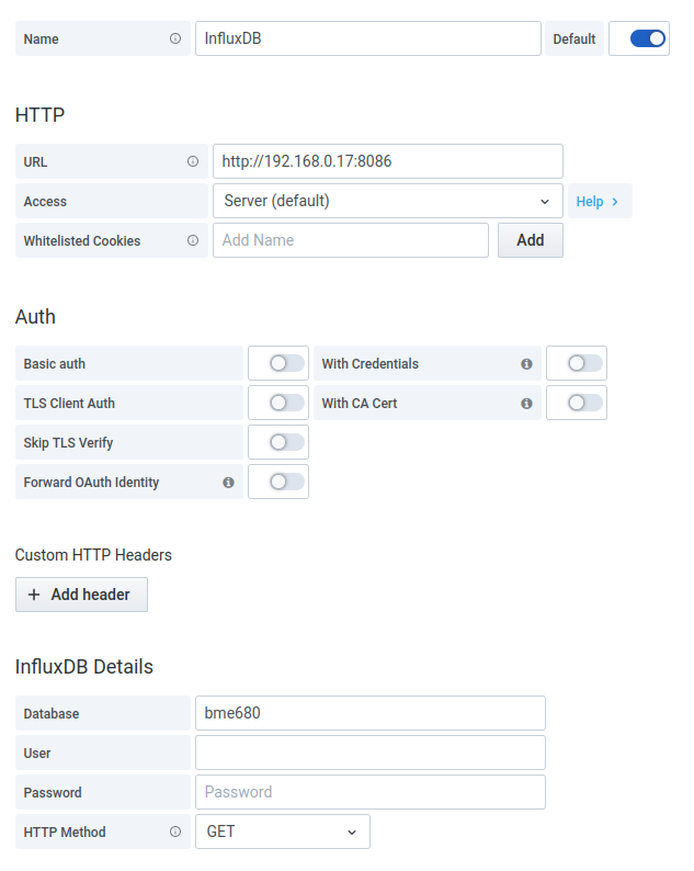
The settings you'll need for the Influxdb connection
Then create a new dashboard. On that blank dashboard, select the cog wheel in the top right, and paste this in JSON Model. when you head back to your dashboard, you now should see some pretty graphs that look somewhat like what I promised.
Let me know how you got on!
Let me know what you thought! Hit me up on Mastodon at @kn100@fosstodon.org.