DeskOps: Commanding My Desk with HTTP - How I Brought Hysteresis Problems to the Desk Where I Solve Hysteresis Problems
BE CAREFUL! This post has been marked as potentially dangerous either to health or the devices discussed. You follow this post at your own risk.
I have a standing desk, but I’ve always wanted a way to automate it, so that I could set up a schedule for “standing” vs “sitting". The controller box itself contains absolutely no smarts, and has no obvious external control mechanism, so I wasn’t really sure how I’d achieve this. This post documents my experience building a system that allows me to do this. It is not intended entirely as a build guide, but more an exploration of what hardware hacking is like for somebody with very little previous experience. Hopefully you’ll learn something from this and I’ll save you some of the time I spent learning this stuff!
What this is
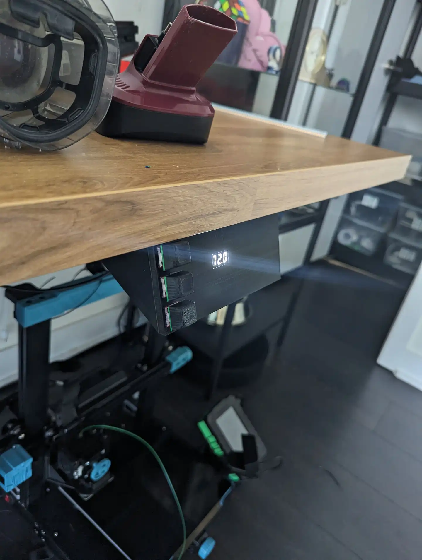
I made a custom circuit board that kind of zombifies the original standing desk controller. It is able to read the current height of the desk from the original controller, as well as pilot the desk up and down. It is controllable via HTTP requests, as well as from buttons on the front of the controller.
GET http://esp32-abcde/desk
{"height":720}

GET http://esp32-abcde/desk?height=780
`OK`
Initial exploration
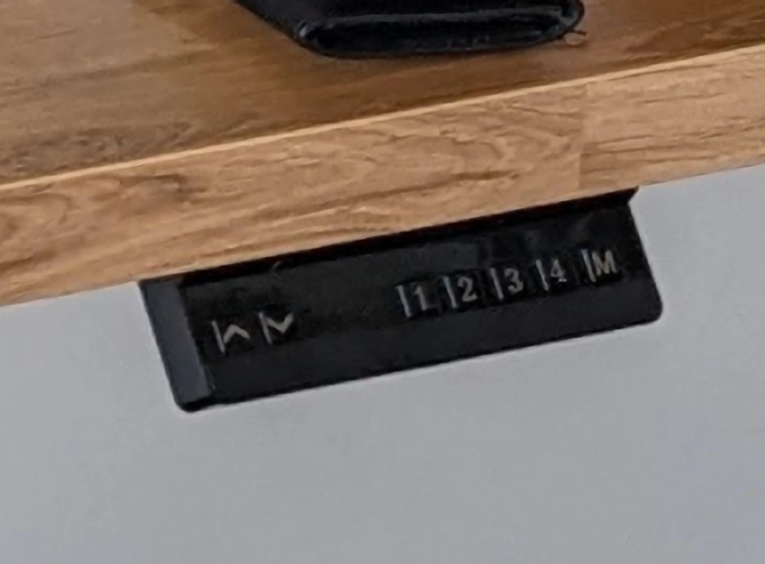
The standing desk I have is a VIVO DESK-V122EB frame with a 2.5m IKEA
countertop placed atop it. More importantly, the controller box my standing desk
has looks like this (Apologies for the terrible photo, I didn’t take any photos
before doing what I did, so this one was cropped from a much larger photo).
After doing some Googling, nothing seemed particularly relevant to my specific standing desk, and other solutions I found involved strapping motorized button pressing robots to the controller, so I decided to open up the controller box and take a look to see if I could do something smarter.
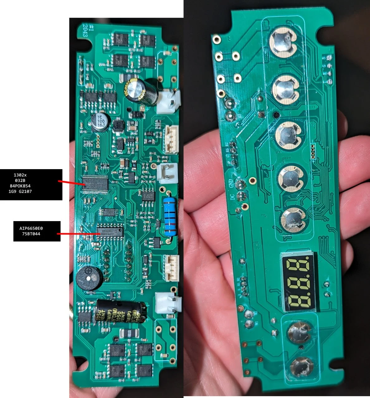
Looking at the circuit board, I realised it would be trivial to ‘press’ the up and down buttons from an external microcontroller. All I’d need to do is use a transistor to bridge the contacts of the switch. I really wanted something a bit smarter than that though. I wanted whatever I built to be able to know the height of the desk. After studying the board for a bit and googling the random part numbers on the chips I could see on the board, I identified the AIP650 as the chip responsible for driving the LCD. Fortunately, a data sheet was available for this part, but unfortunately it was in Chinese, a language I do not speak.
According to the data sheet, translated with DeepL, it receives data in an i2c ‘like’ format, and then drives a 3 segment LCD just like the one on this board based on what data it received. I was unable to determine from the data sheet what the data being sent to the controller actually “meant”, but wasn’t worried about that for the moment. I just wanted to capture the data.
For those not familiar with hardware, I2C is the scheme by which most circuits use for inter-chip communication. In my desk controller, there is a microcontroller which writes data to a LCD driver chip, which in turn lights the correct segments on a 3 digit segmented LCD. How would I capture the data though? Easy, I thought! All I had do to was hook up to the same two pins the data sheet reported as being the i2c pins along with the grounds of the standing desk controller and my esp32, and I could then “sniff” the data that was being sent across the i2c bus, decode it, and then use that for something useful.
So away I went! I soldered two wires directly to the pins on the chip that were marked as the data pins (I am deeply sorry to anybody offended by my soldering job!), and soldered a third wire to a ground point on the board. I then connected those wires to an ESP32, and then went looking for somebody elses code to try to sniff the i2c data to see if this was even possible.
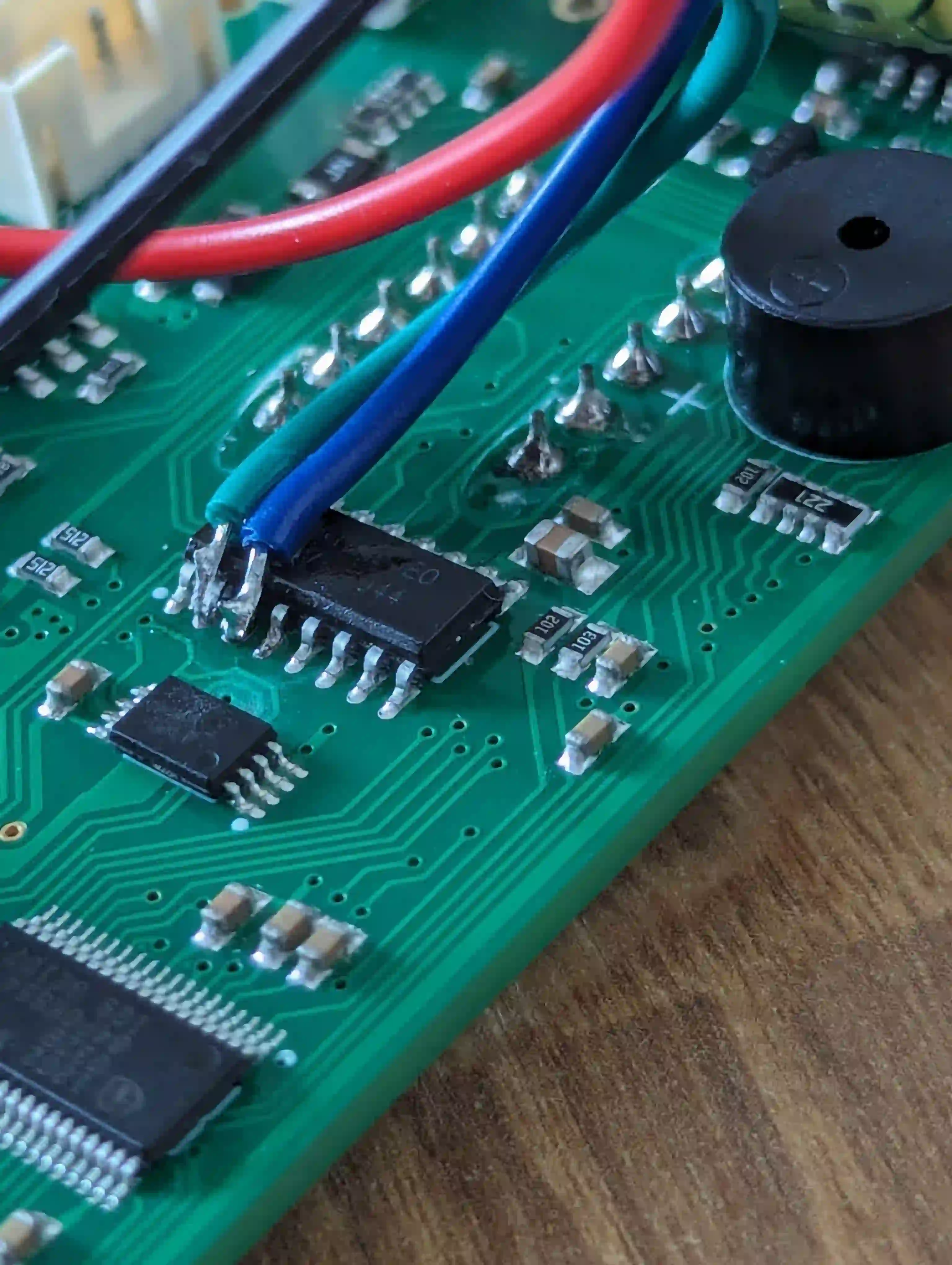
I came across one such project online, which just about worked. It would output what looked like plausible i2c data, but would constantly crash or start outputting total nonsense. At this point, I hadn’t really understood I2C, nor did I understand the code here at all, so the fact it worked even a little bit I took as a win.
At this point, I still hadn’t really considered how the code worked at all, so I then took the plunge into the code and figured out its method of operation, so next I took a dive into the world of I2C.
A quick look into I2C
If you understand I2C even a little bit, you probably understand it better than I, so you can skip this section.
In I2C communication, there are two pins involved. One is the clock pin, usually
referred to SCL, and the data pin, referred to as SDA. The participants on
an I2C bus are known as controller devices, and target devices (although are
commonly referred to as master/slave in data sheets and the such!). Controller
devices write to the I2C bus, and target devices listen for writes that are
targeting them. Target devices do respond on the I2C bus, but this is to just
acknlowledge they correctly received data. Remember that this is digital data -
so the controller can only pull either of the pins high or low, which literally
means “emitting voltage” or “connected to ground”. It emits a clock signal
(continuous pulses on the SCL pin), along with varying pulses on the SDA pin for
signalling.
Let’s review one I2C communication session:
-
A controller wants to communicate with a target. IT first must assert control of the bus. To do this, it first pulls SCL high, and then pulls the SDA line high, then pulls it low. This transition of SDA from high to low while SCL has been held high implies a master is about to broadcast data, and targets know to listen for incoming data.
-
The controller needs to let all those target devices listening know which device it wants to talk to. It does this by sending 7 bits of data which correspond to a device address, along with 1 bit to indicate whether it would like to read or write to that specific device. It transmits these bits of data by pulling SDA either high or low to indicate a 1 or 0, along with a clock pulse (pulling the clock from low to high). This triggers the target device to read the value that is present on the SDA pin, thus transmitting a byte.
A note about addresses: They’re not always 7 bits, and sometimes can be 10 bit. They’re usually hardcoded into whatever target device is receiving them - and for hobbyist grade Arduino attachments, you can even configure the address through jumper pins or switches, allowing you to connect more than one of the same device to an i2c bus.
-
Next, the target with the correct address must ACK this transmission, to signal to the controller that it is ready to receive data. The target does this by pulling the SDA pin low, which the controller interprets as an ACK. If no target ever does this, the controller should assume it wasn’t heard for some reason.
-
Assuming the target ACKed the transmission, meaning it recognised the next data on the I2C bus is intended for it, the controller proceeds to transmit a data packet. IT transmits 8 bytes of data following the same scheme as the address transmission above, and again waits for an ACK condition the same way. If there is more than a single byte of data that needs to be transferred, it just transmits the next 8 bits after receiving the ACK. This cycle can happen an arbitrary number of times.
-
The controller is now done transmitting to that particular I2C device, so it needs to signal that. It sends a stop condition. This is similar to the start condition described above, except this time we pull SCL high, and then pull SDA high. The transition of SDA from low to high while SCL was held high indicates the transmission is over.
Digging deeper into the desk
Knowing all of this now, I decided to refactor the code sample above into a form that was better understood by me, which ended up turning into this project.
A quick discussion on how this code works. Since we only really care when the state changes on the pins we are sniffing (SDA and SCL) we can get away with using interrupts. An interrupt causes the CPU to halt execution of whatever it was doing, switch to some other context, do some other processing, and then return back to the main program loop. In our context, we want interrupts that trigger on state changes for the I2C Pins. Realistically, there are only two events we only really care about:
How we detect start and stop conditions: SDA changing from HIGH > LOW or
from LOW > HIGH triggers the interrupt i2cTriggerOnChangeSDA(). If SCL was
LOW, this isn’t a start or stop, so just return. If SCL was high, depending on
the current bus state (discussed later), along with whether SDA is high or low,
we record a Start or Stop to a buffer. Concerning the bus state: we initially
assume the bus is IDLE, and move to TX if there is a start condition detected.
If a stop condition is detected, we move to IDLE)
How we detect data being transmitted: SCL changing from Low > High
indicates that there is data for us to read. so, the transition triggers the
interrupt i2cTriggerOnRaisingSCL(), which checks the bus state. If it was set
to TX by i2cTriggerOnChangeSDA(), we read whatever data is present on SDA pin
and write it into the buffer
This results in a stream of data, and very quickly a buffer overflow. To resolve this, we need some code that processes that buffer and does something useful with it. We can only do this processing with the I2C bus is idle, so, in the main program loop, we wait for the IDLE bus condition to be reported by the interrupts above. Once we have that, we can safely parse through the buffer, and do something with the data. In the example code above, it just prints whatever it got to Serial. Once it’s caught up with the last written position of the buffer, it resets the variables that keep track of where the buffer was last written to and read to, so that we can continue to use that same memory over and over.
The code did as I asked and outputted streams of 1s and 0s along with start and stop conditions to the screen, but I had no idea what any of it meant, nor if the code even worked. What I could see is that there seemed to be bursts of data, and if the data was to be believed, at least 5 I2C addresses receiving data.
I lamented this fact in a conversation with a colleague (if you’re reading this, you know who you are, THANKS!), and he suggested I pick up a Logic Analyzer. I had no idea what a logic analyzer was, but for years I’d looked on in envy as others used their logic analyzers for interesting hacking related tasks, and thought that stuff was way too complicated for me. I’d never gotten one because I was afraid of buying it, realizing I was way out of my depth, and it becoming “that thing I bought that I have no idea how to use”.
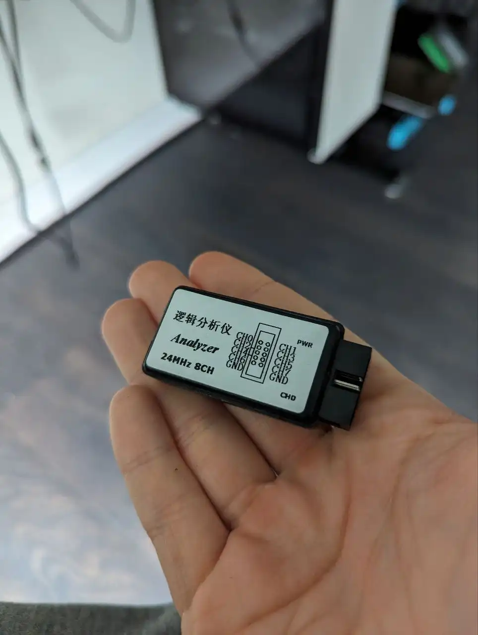
This time however I bit the bullet and bought the cheapest logic analyzer I could. I had no idea how to use the thing when it arrived, but I discovered that Pulseview is a piece of software that can be used for logic analysis. I connected the SDA and SCL pins of my desk up to my logic analyzer, connected it to my computer, fired up Pulseview, and clicked around a bit. Almost immediately, I figured out how to “sample” the data the logic analyzer was getting, as well as that Pulseview includes a super handy I2C decoder built right in!
So, I sampled, and lo and behold, roughly what I’d been observing with the esp32 sniffing code was visible here too! Short, sporadic bursts of data. Again, sorry for the photos, you might want to right click and open them in a new tab so you can arbitrarily zoom them!

Zooming in, even more success! Comparing what my code was outputting to what was being seen on the logic analyzer, I could see the same addresses and the same data packets. Incredible. It seemed that in my particular case, each address received exactly one byte of data, and that the NACK/ACK bits didn’t seem to make a lot of sense. I wonder if this is what the creators of the AIP650 meant when they said it was ‘i2c-like’.

I still had no idea what any of this meant, so I flailed about for a bit. After a bit of thinking, I theorised that perhaps the AIP650 chip was not “one” i2c device, but instead was at least three, one per segment. That way, the microcontroller that was asking it to display stuff could update each segment as it needs to. It kind of made sense. A segment of the LCD consists of seven segments, along with a period that appears beside that segment. That’s 8 bits of information, so maybe each segment is linked to a specific bit in the byte.
To test that theory, I got the rightmost segment to display a zero, and sampled using the logic analyzer. I dumped the data out of Pulseview, and proceeded to make the segment display a 1, rinse and repeat all 9 digits. I wrote all the data I got into a spreadsheet (this took a while) in the hopes I could spot a pattern.
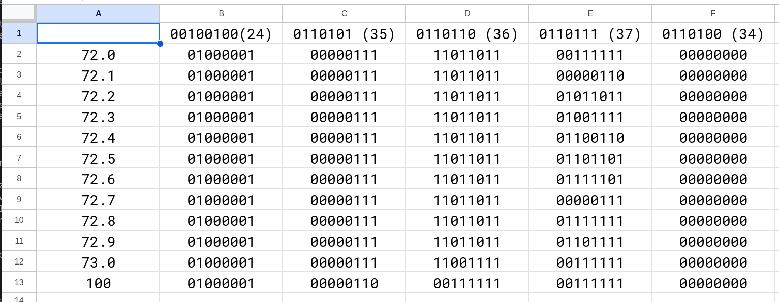
This allowed me to confirm that a specific pattern of bits corresponded to the numbers 0 through 9, and also allowed me to identify which i2c address corresponded to which position on the display (the digit), as well as allowing me to identify that the most significant bit in the byte corresponded to the period portion of the digit. This is decent progress, I thought!
What it didn’t do however was tell me which bit corresponded to which individual segment of a digit. Figuring that out was kind of like solving a Sudoku. I sat there with a sheet of paper, drawing the digits as segments 0 through 9, trying to find the commonalities.
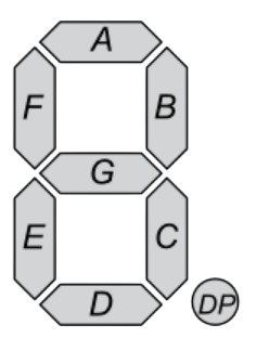
As an example of what this particular puzzle took, let’s work through
identifying two segments of a digit. We see that when the digit 1 is present
on the LCD, the binary 00000110 is present. That must mean that the 6th and
7th bit correspond to the segments B and C, but we don’t know which is which. To
determine which, we now have to find a digit which only had either B or C
illuminated.
The digit 5 proves to be a good candidate here, since C is illuminated, but
B is not. Looking at the data we collected, 5 seems to be represented by
01101101. The 6th bit is 1, the seventh is 0, meaning that the 6th bit must
then be C, and B must therefore be represented by the 7th bit. Continue this
process of deduction all the way and you’ll eventually figure out which bit
represents which segment. In my case, each bit in the array represented the
following segment:
- Position 0: DP
- Position 1: G
- Position 2: F
- Position 3: E
- Position 4: A
- Position 5: C
- Position 6: B
- Position 7: D
Now that I knew what the binary data meant, I was finally ready to decode it. I wrote some code that would parse each I2C frame in the buffer into the address portion to figure out which segment was being written to, and then parse the data portion into a character. I don’t have the code I wrote back then, but here’s the most recent revision showing how we turn the data portion into a digit, along with the code that parses through the buffer
Next up came actually raising and lowering the desk. I’d already done this sort of thing before, having previously tasked an ESP32 with pressing the button on my USB switching hub so this part was going to be relatively simple.
All you need to do really is take a transistor, connect the collector and
emitter to your switch contacts, along with connecting the base to one of your
ESP32s GPIO pins (through a resistor to limit current, 10k will do!). Then, in
your ESP32 or Arduino code, all you need to do is configure your pin as an
output pin, ie: pinMode(yourPinInt, OUTPUT);, and then when you want to press
the button, you just bring the pin high by using digitalWrite(yourPinInt, HIGH);. To stop pressing the button, you bring the pin low
digitalWrite(yourPinInt, LOW);.
The electronics assembly
On my particular standing desk, the switch contacts consisted of an outer and inner ring. I determined that the outer ring was positive 5v, and was common across the switches. The inner ring however was not common. Therefore, if I wanted my desk to go up or down, I needed to bridge ANY of the outer rings to the center contact of the up and down switch. I firstly tested my design on a Breadboard:
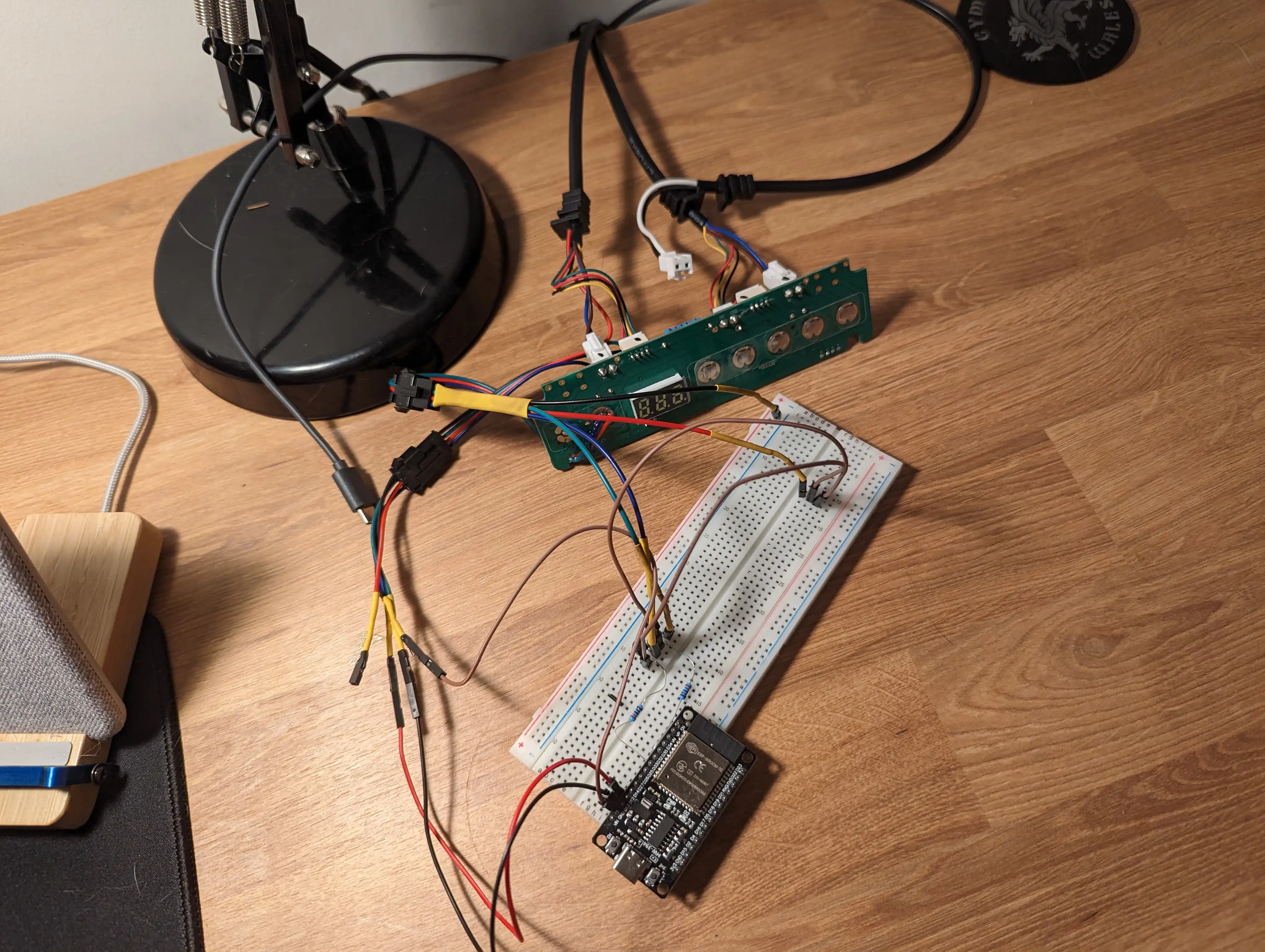
After validating this worked, I soldered together a protoboard. I firstly attached my ESP32. I then soldered two resistors to D33 and D32, and then connected the center pin of both transistors (the base) to each resistor. I connected the collectors of both transistors together (the leftmost leg, with the flat side of the transistor facing you), and connected those legs to the outer ring of one of the switches. I then connected each Emitter leg to the center ring of the up and down rings.
I also soldered D12 and D13 to the SDA and SCL pins on the AIP650 present on the
desk controller, along with a wire to VIN which would later supply 5 volts,
along with a ground pin.
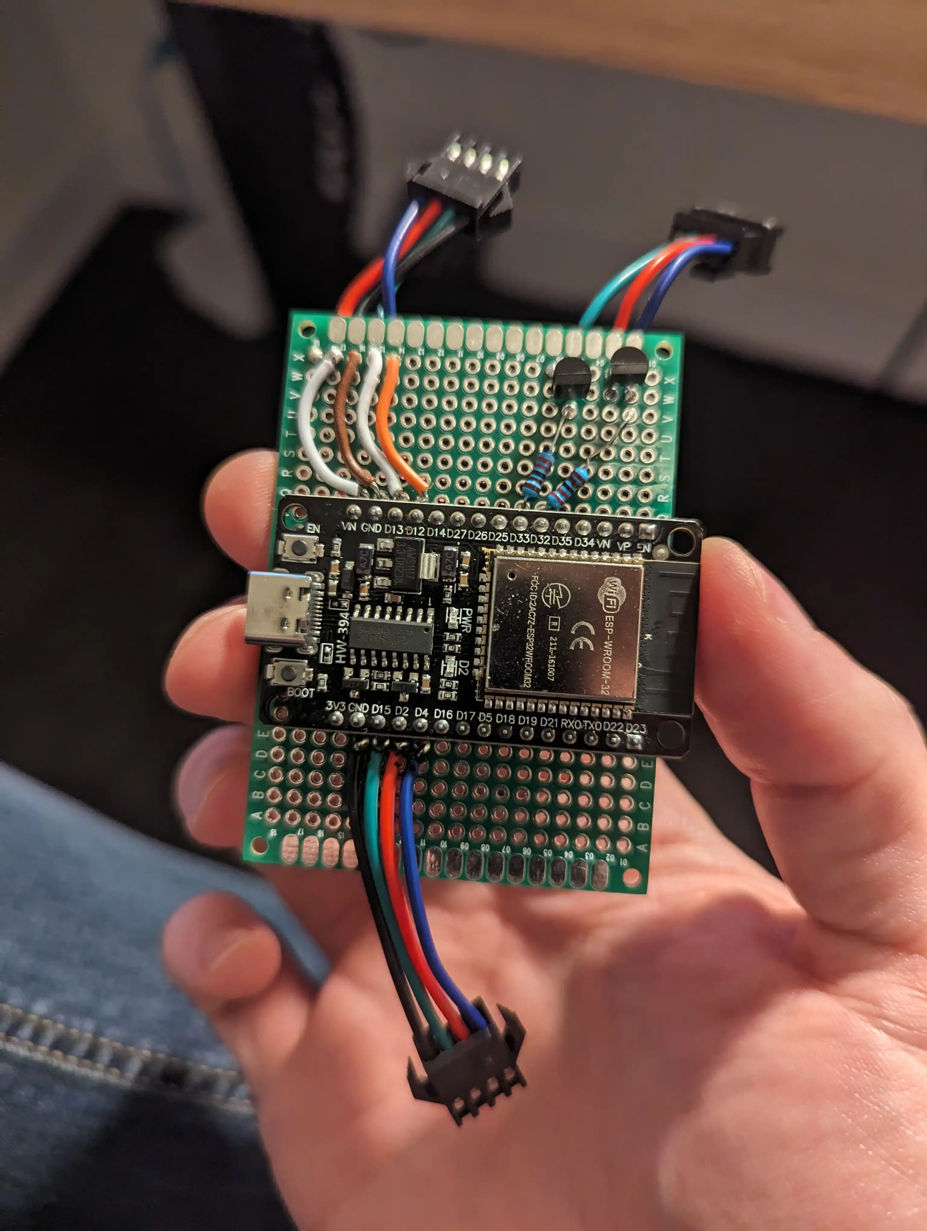
I also attached wires to D15, D2, and D4, along with a second ground connection
- which I will later attach to three switches, allowing me to have buttons on the outside of my new controller to control the desk manually, as I could before. I didn’t bother connecting any of the other buttons of my desk to the ESP32 since I didn’t care about the functionality they exposed (presets and the such).
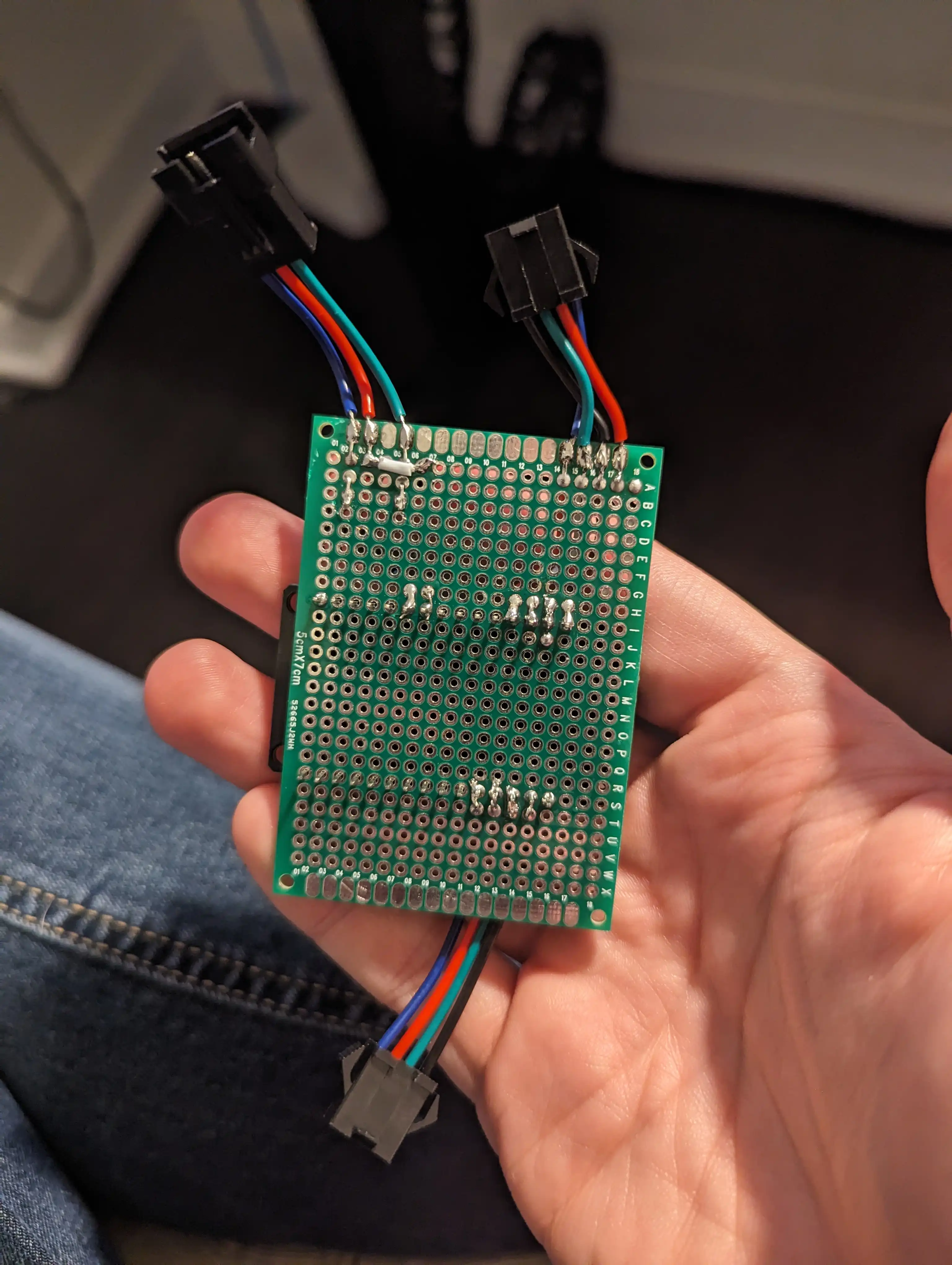
Once all this was complete, and it continued to work, it was time to write some code.
The code
My first revision of the code was a rats nest. I have no idea what I am doing in
C++ (I’m a Golang/Ruby baby!), but its method of operation was very simple. It
had two main variables responsible for control, the currentHeight, and
requestedHeight. If they were not equal, the code would press the button that
would cause currentHeight to move in the direction of requestedHeight, and
release it once they were equal. Can you see the problem with this technique?
If not, no worries, I clearly didn’t see it coming either, and I really should have, given it’s a very common problem in DevOps land. We regularly deal with a concept called hysteresis, which is effectively a lag between an input and a desired output. If you’re more familiar with servers, maybe this example will help. Imagine you scale the number of replicas in a particular deployment based on a really simple metric like CPU utilisation. You might have some sort of rule like “If the CPU utilisation average hits 80%, add a replica. If it is below 80%, remove a replica. Then, when your clever autoscaler recognises that the average utilisation has exceeded 80%, it dutifully adds a replica. The utilisation then drops below 80%, and a replica gets removed, bringing the utilisation back up over 80%. This cycle repeats ad nauseum until you just use an autoscaler written by someone else.
Well friends, I had hysteresis in the form of a 2.5m long oscillating vibrating
desk. The code frantically tried its best to make currentHeight equal
requestedHeight, but all it did was cause my desk to oscillate up and down
frantically until it eventually overheated and refused to do anything for around
an hour after this event.
As hysterically funny as I found this, I really didn’t want to break my desk, so I went back to the code and tried to fix this.
The fix I came up with was stupid, but it works. The ‘proper’ solution is probably a PID controller, but the solution I came up with is far simpler to write and works perfectly, so I don’t really care. I just implemented a form of crude PWM on the button pushes! Conceptually, instead of holding the button until we see the target height, we instead hold the button until we are near the target height, at which point we start rapidly pressing and depressing the button, which has the effect of causing the desk to move more slowly. We keep doing this until we reach the target height, and then we’re done, without overshooting or undershooting the target.
Something else I learned the hard way is that my desk controller really does not appreciate having its button pressed and depressed at the clock speed of the ESP32, and it gets really confused and sad. This was simple to resolve though just by modifying the code to press and depress the button with a 50ms cycle time.
Through all this, I ended up with some code where I could program the ESP32 with a given height, and after I reflashed the ESP32, it would command the desk to a particular height.
I obviously wanted a way of setting this value arbitrarily, so I set up a simple HTTP web server that would do this for me, hosted on the ESP32. It sits there, waiting for requests, and if it receives a height change command, it does exactly as I described above and it worked beautifully.
3D printing an enclosure
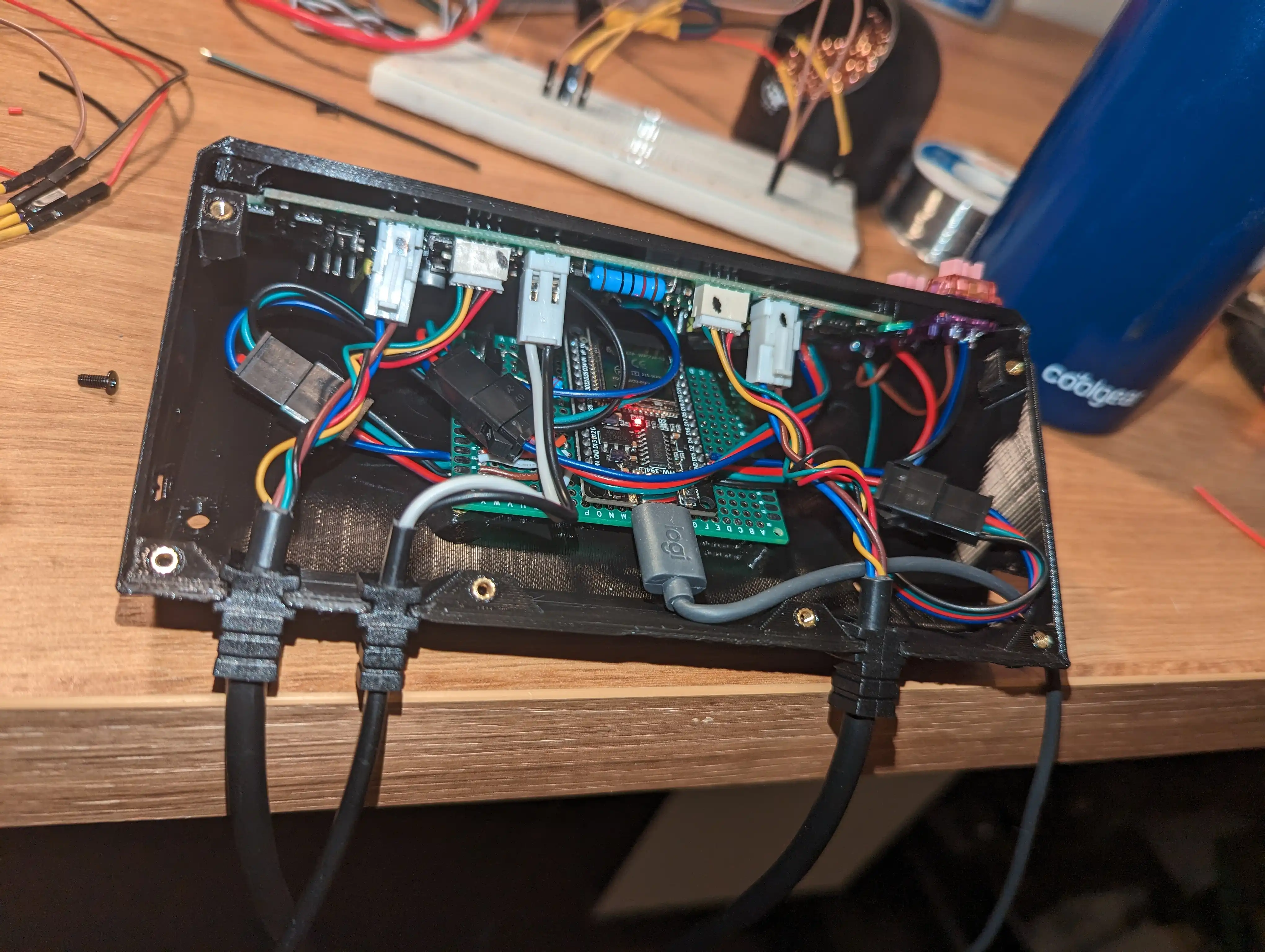
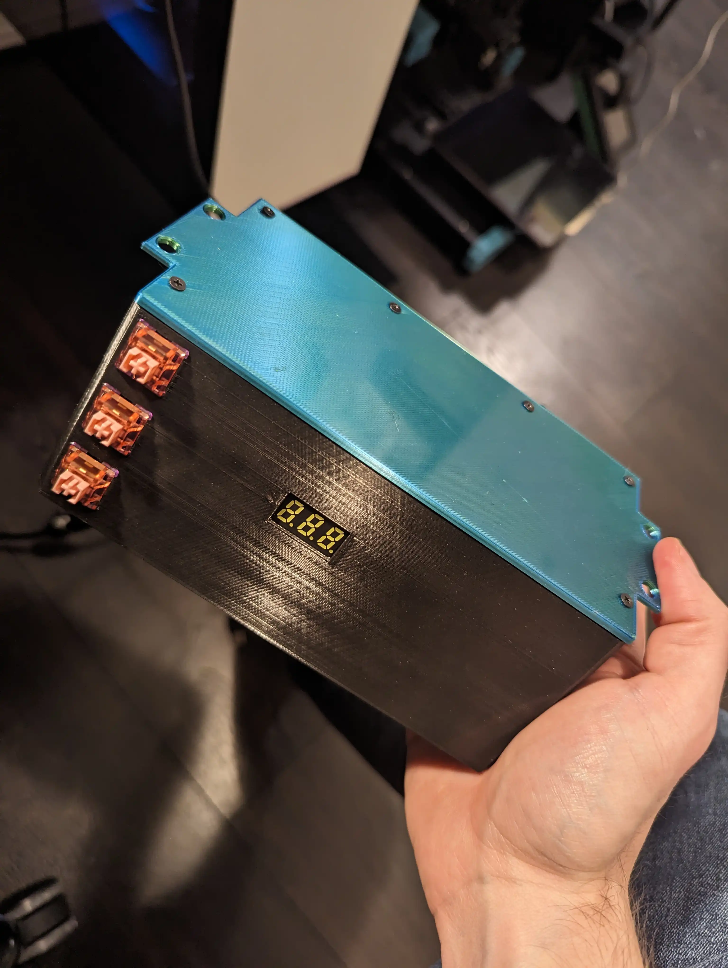
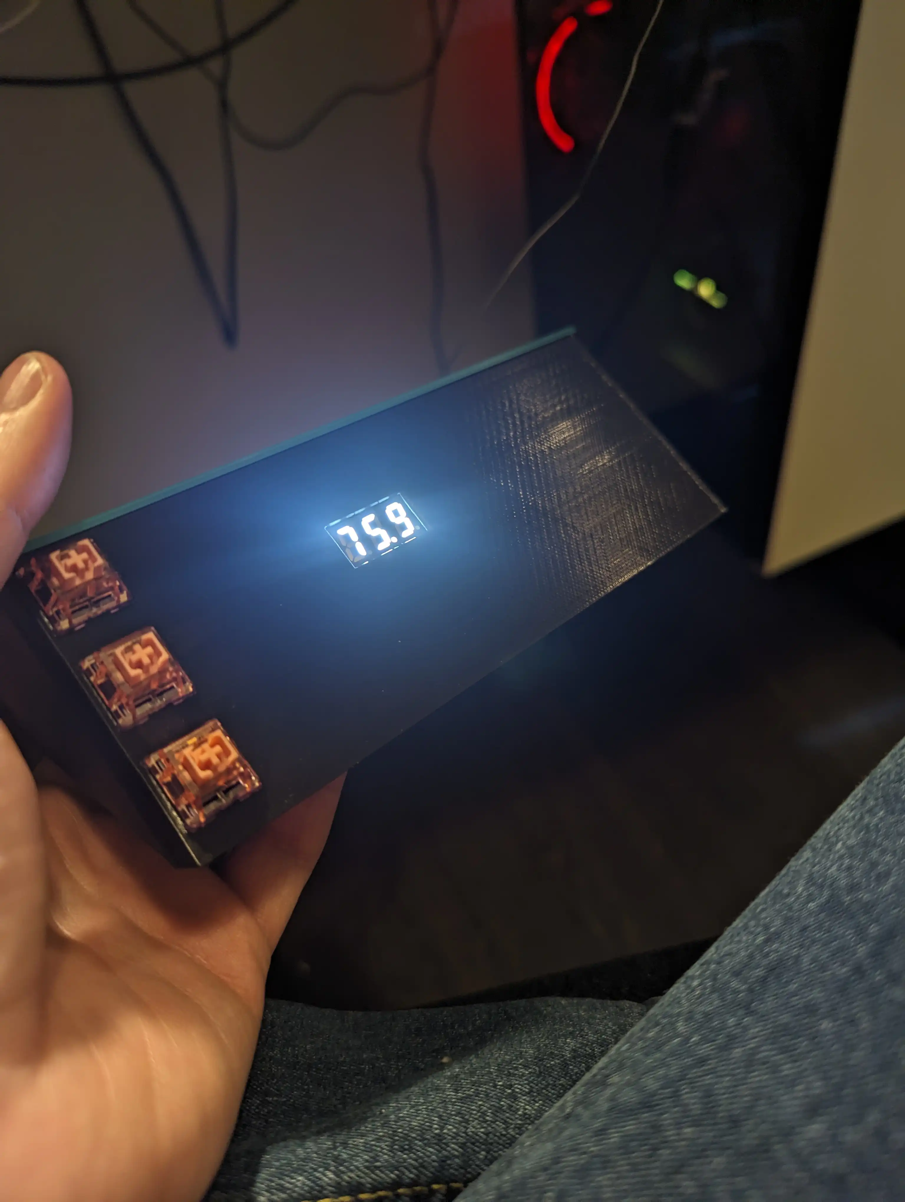
CAD modelling is something I also have no professional experience with. I’ve been teaching myself over the last few months, and decided this was the perfect opportunity to model something relatively complex. What I wanted was a place to put the original controller board so the LCD was still visible, spots to put 3 real mechanical keyboard switches (yes, the kind you find in a keyboard :P), and a spot to screw in the protoboard construction documented above.
I came up with this. Beauty is in the eye of the beholder, I guess! I threw the job to my trust Sovol SV07 and waited a few hours. It turns out I designed something that is a nightmare to print, but the printer did an admirable job even with my ridiculous design. It’s impressive what modern 3D printers are capable of!
I then assembled everything pretty much as described, just with the addition of 3 mechanical keyboard switches, and it all went together mostly as designed. The print quality is frankly terrible. This was down to a misconfiguration of the printer, as well as the fact that this is a fairly difficult to print model. I was also being impatient and printing it at ludicrous speeds. 3D printing is a hobby that really benefits from patience, something I sometimes lack.
I have not released the STL for this particular enclosure, because it is an absolute nightmare to print, and has some design errors I haven’t addressed. If you really want it for some reason though, I will give it to you. Just ping me on Mastodon.
I’m finished, right?
Great! Install and done right? I thought so too. I installed it, and revelled in telling anyone who would listen that now desk go up and down when I send HTTP request to it! Cool right? RIGHT?!. It worked great.
Until disaster struck. A few hours after I installed it, my desk started going up on its own. I was happily coding away, and it started going up totally on its own. No command. WTF?!
I frantically unplugged it and started trying to think about why this happened.
I racked my brain, but I couldn’t think of any reason. Through sheer luck it
happened a second time while I was watching the serial output from the ESP32. I
had it logging out the state of the currentHeight and requestedHeight
variables if they changed, and the currentHeight randomly changed from 720
to 1520! I had focussed all my thinking about reasons why requestedHeight
might change. I hadn’t considered the actual height of the desk was being
misread.
It turns out, writing your standing desk controller the same way you write reconciliation loops in Kubernetes-land is not a great approach. It also turns out, that just by installing your project in an enclosure, you can introduce a brand new problem that was not present previously.
Enough foreshadowing, the problem was pretty obvious in hindsight. Sniffing I2C is not a perfect art. Electromagnetic interference can cause you to incorrectly read a 0 as a 1, or a 1 as a 0. In my case, if this happens, in the best case, we read an invalid I2C address, which just means we ignore that frame of data since we only care about a subset of i2c addresses (the ones that correspond to each portion of the LCD). In the next best case, the actual data portion gets corrupted somehow, and we get an arrangement of segments that does not correspond to a valid digit. In this case, we again just ignore that particular frame, and nothing bad happens. The most insidious cases though are where a data frame gets corrupted, and we end up reading the wrong digit.
Given my code works like a reconciliation loop, it notices that the current height does not equal the previously requested height, and frantically tries to correct for that; but of course, it’s reading invalid data, so desk go up even though I didn’t ask it to. Oh noooo.
I have made this situation extremely unlikely by adding a number of safety checks:
- If a new currentHeight comes in that is substantially different to the previous reading, we assume that new reading was invalid. Usually, the next frame of data is read correctly, so this catches most cases.
- If a new currentHeight comes in that is out of bounds (ie, is a value the desk should never display), we just ignore it. This happens quite frequently, since one of the most common errors I’ve seen is reading the first digit as a ‘1’ instead of a ‘7’ (a single bit different!).
- We only move if we have received a command to do so. CurrentHeight can change however it wants outside of a move command, we don’t care, unless the user has issued a move request. Once the desk has reached its requested height, we make sure the desk has stopped moving, and then stop caring about currentHeight changes until the next request comes in.
This has resolved that specific problem! It’s always good to remember to anticipate your hardware misbehaving and adding basic sanity checks to your code.
The code today
I reiterate from earlier, I do not really know C++/C or hardware, so this code is probably a litany of sins. Correct them in PRs if you like, I might even flash them to my desk, because those are words I can say without sounding insane now! So, when reviewing this code, bear that in mind. https://github.com/kn100/desksniffer/
But why?
Let me know what you thought! Hit me up on Mastodon at @kn100@fosstodon.org.